Program interface overview
Program interface overview
Home Page: BLZ Dental Logo

New Order Page:
Patient Mode

- Fill in patient’s name (required), the technician’s name and notes in the area ①. The creation date and order ID are generated by the system.
- Choose the Patient Mode or Multidie Mode in the area ②.
- Choose the tooth needed in area ③. Click “Clear All” to clear the information of all the selected teeth. Click “Clear Current” to clear the information of the current selected tooth.
- Notice: Click the curve between the tooth position number to add the bridge information.

- Choose the restoration type needed in area ④.
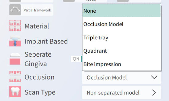
- Choose the Material, Implant Based, ON/OFF of the Separate Gingiva and Multidie mode, Occlusion and Scan Type in area ⑤.


- New Order: Create a new order
Save: Save the current order. The order can only be saved when the order information is filled properly.
Scan: Click “Scan” to enter the scanning process. You can only start the scanning process after saving the order.
Multidie Mode

- Differences compared to Patient Mode:
- Choose the hole for the die on the multidie plate instead of the tooth position.
- There are only 4 restoration types.
Order List Page:

- Delete orders in batches in area ①.
- Search the order by patient’s name in area ②.
- View current order in area ③ .
See: view the model of the current order and trim it according to your needs.
Delete: delete the current order.
File: view the storage path of the scan model file.
Setting Page:
Scan Settings

- Texture
ON: the color and handwritten marks can be showed.
OFF: the color and handwritten marks cannot be showed.


- Scan Mode:
Fast Mode: the scanning speed is faster.
Fine Mode: compared to fast scan, Fine Mode can scan the model from more angels and the scan data quality of complicated models is higher.
- Priority Antagonist:
ON: scan the antagonist model first.
OFF: scan the working model first.
- Priority Gingival:
ON: scan the model with gingival first, and then the model without gingival.
OFF: scan the model without gingival first, and then the model with gingival.
- Calibration: click “Start” to open the calibration page and start the calibration process.
- Debug: used by engineers when there’s any problem with the software. (You don’t need to use this in normal scanning process.)
General Settings

- Output Path: choose the path for saving the scan model file.
- EXO DentalCAD Path: bind the LS100 software with EXOCAD, and you can open the scan model directly in EXOCAD without exporting the file.
- Language: Chinese, English and Turkish are available for choosing.(The languages choice is different in different versions of software.)
- Export File Format:
PLY, OBJ: Texture
STL: No texture
- Order File Naming Field: the patient’s name and the technician’s name can be included. (This setting can affect the choosing of the start field of the order name.)
- Order Name Start With: choose the date, patient’s name or the technician’s name as the start field.
Help Page:
- Manual: you can check the user manual here.
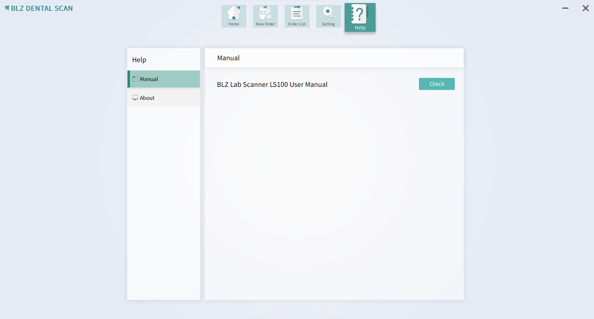
- About: check the software version and view our website by clicking the link.

Scan Page:

- ①Scanning workflow: Prepare for the next step by following the workflow.
- ②Choose the Scan and Texture mode according to your needs.
- ③The real time image window: check the model and make sure it is in the middle of the image window before starting the scan.
- ④Example of how to insert the model: choose the right clamping plate and way of placement according to the example.
- ⑤Click “Scan” to start scanning.

- ⑥Additional scanning: you can do additional scanning at the areas with holes. There are Auto and Manual additional scanning modes available for choosing.
- ⑦Trimming Tools: Choose one of them and trim the model.

- Align Die Manually: For dies that can’t be matched automatically, we can do the alignment manually.
Steps:
Firstly,choose at least three points on the die (not on the same line) and on the same position of the model correspondingly.
Secondly, click “Match” in the area ⑧.
Then, the manual alignment is done.

- ⑨Toolbar: From the top to the bottom: Model View, Manual Fill Hole, Margin Line Detect, Undercut Detect and Block Out.
- ⑩Auto fill hole: Choose a proper radius size (2,4 or 6) that is bigger than the holes that need to be filled, and click “Apply” to start the Auto fill Hole process.